In this tutorial you will find a step by step guide on how to create a bevel gear in SolidWorks by using 3D features. Fundamentals of Bevel Gear Design. Bevel gear design procedure.
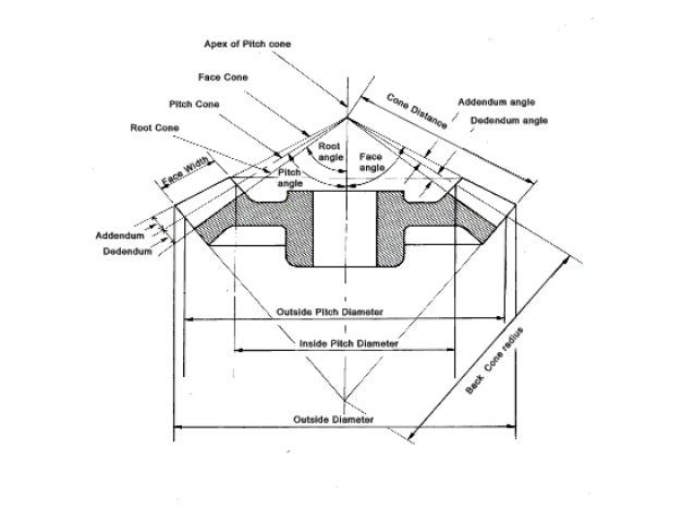
Bevel Gear Design Procedure, All bevel gears are designed using a reference right cone called the pitch cone The pitch cone is used as a basis for describing all other geometric entities of the bevel gear. Transmission power input and output speeds. Bevel Gear Design Procedure - YouTube. Schultz All rights reserved.

110 depicts a typical miter gear arrangement. Exercises in calculating gear dimension sheets the use of Gleason time sharing computer programs and the evaluation of resulting stress data. About Press Copyright Contact us Creators Advertise Developers Terms Privacy Policy Safety How YouTube works Test new features Press Copyright Contact us Creators. Basic understanding of the design elements of bevel and hypoid gears.
Fundamentals of Bevel Gear Design.
Read another article:
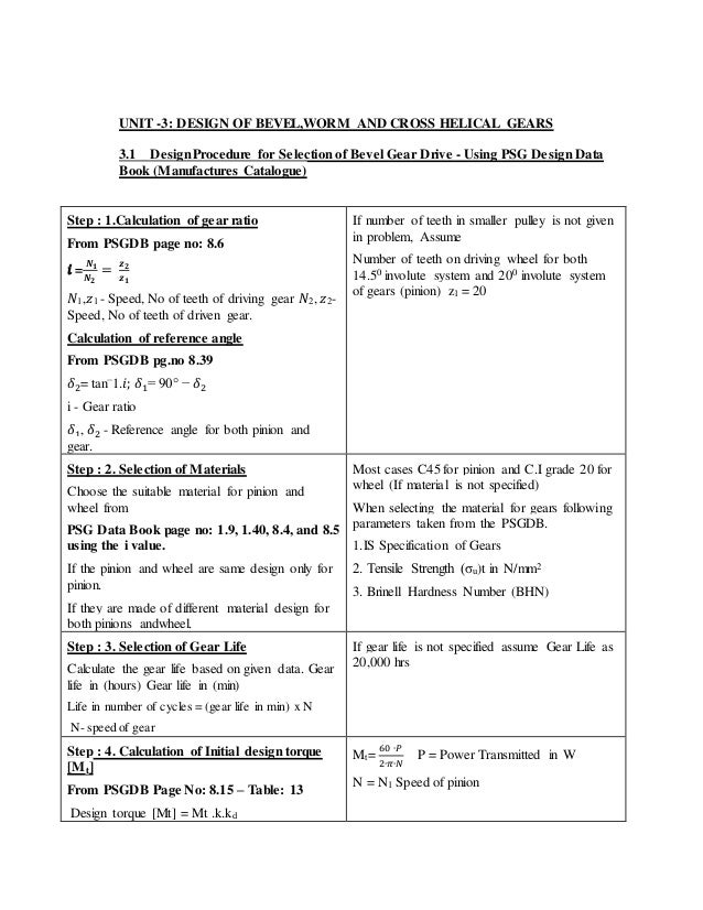
The number of teeth in pinion can be assumed to be 20. γ 1 γ 2 Σ γ 1 2 in case of a 90 shaft angle. Calculation of gear ratio i. Clarify specifications and determine basic elements. Check spur gears strength.
 Source: sdp-si.com
The sum of the pitch angles of spiral bevel gears is equal to the shaft angle. The specifications for the design are the power requirements the gear ratio pinion speed and the material properties. The objective of this project was to develop an automated process for modeling spiral bevel gears to reduce gear design time. The sum of the pitch angles of spiral bevel gears is equal to the shaft angle. Helical Gear Calculations Crossed Helical Gear Meshes And Bevel Gearing Sdpsi.

Is outlined as follows. Transmission power input and output speeds. The pitch surface of bevel gears is a cone. To optimize the performance of any two bevel gears the gears must be positioned together so that they run smoothly without binding andor excessive backlash. How To Determine The Module Of A Spiral Bevel Gear Set Quora.
 Source: pdfprof.com
Introduction to Gear Design For information contact. Transmission power input and output speeds. Where n a and n b speed of the driver and driven respectively and z a and z b number of teeth on driver and driven respectively. Where N A and N B speed of the driver and driven respectively and Z A and Z B Number of teeth on driver and driven respectively. Design Procedure Of Helical Gear.
 Source: youtube.com
The pitch surface of bevel gears is a cone. Estimating the dimensions of pair of straight bevel gears. I recommend that you play around and try to create different cogs and gears. To optimize the performance of any two bevel gears the gears must be positioned together so that they run smoothly without binding andor excessive backlash. Bevel Gear Design Procedure Steps How To Calculate Module Of Bevel Gear Youtube.
 Source: sciencedirect.com
Design procedure for bevel gear. I recommend that you play around and try to create different cogs and gears. All bevel gears are designed using a reference right cone called the pitch cone The pitch cone is used as a basis for describing all other geometric entities of the bevel gear. The main disadvantage of the helical gear -. Bevel Gears An Overview Sciencedirect Topics.
 Source: youtube.com
Helical gears are superior to spur gears in most applications especially where noise must be kept to a minimum or the pitch line speed is in excess of 10 ms. Calculation of gear ratio i. Where NA and NB speed of the driver and driven respectively and ZA and ZB. The objective of this project was to develop an automated process for modeling spiral bevel gears to reduce gear design time. Bevel Gear Design Procedure Youtube.
 Source: slideplayer.com
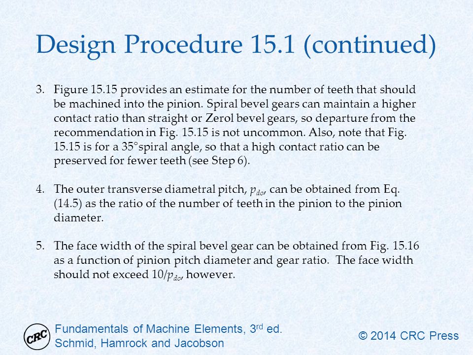
DESIGN PROCEDURE FOR HELICAL GEAR. Select the number of teeth for the pinion and the g. The specifications for the design are the power requirements the gear ratio pinion speed and the material properties. Bevel Gear In SolidWorks Exercise 5 in SolidWorks. Chapter 15 Helical Bevel And Worm Gears Ppt Video Online Download.
 Source: researchgate.net
110 depicts a typical miter gear arrangement. The main disadvantage of the helical gear -. About Press Copyright Contact us Creators Advertise Developers Terms Privacy Policy Safety How YouTube works Test new features Press Copyright Contact us Creators. Average module mav can be calculated based on the beam strength using the equation DESIGN PROCEDURE FOR BEVEL GEARS 5. Concept And Reality Flowchart For Straight Bevel Gear Design Download Scientific Diagram.
 Source: studylib.net
The pitch surface of bevel gears is a cone. The design variables are the number of pinion. Design a pair of bevel gear which is used to connect two shaft at right angles and transmit P 50 kW power from an induction motor to a conveyor belt. Design procedure for Bevel Gear. Design And Analysis Of A Spiral Bevel Gear.
 Source: slideplayer.com
Design of peripheral structures of gears. Exercises in calculating gear dimension sheets the use of Gleason time sharing computer programs and the evaluation of resulting stress data. The specifications for the design are the power requirements the gear ratio pinion speed and the material properties. Consulting Table 53 knowing the gear ratio i choose the suitable material. Chapter 15 Helical Bevel And Worm Gears Ppt Video Online Download.
 Source: semanticscholar.org
Design of peripheral structures of gears. Bevel Gear Design Procedure - YouTube. Design procedure for Bevel Gear. DESIGN PROCEDURE FOR BEVEL GEARS From the requirements choose suitable materials for pinion and gear tooth profile and pressure angle are selected. Figure 16 From Design And Analysis Of A Spiral Bevel Gear Semantic Scholar.
 Source: researchgate.net
Design a pair of bevel gear which is used to connect two shaft at right angles and transmit P 50 kW power from an induction motor to a conveyor belt. About Press Copyright Contact us Creators Advertise Developers Terms Privacy Policy Safety How YouTube works Test new features Press Copyright Contact us Creators. Design of peripheral structures of gears. As the popularity of five-axis CNC machine tools and multi-axis CAM software has increased such tools are now being used to manufacture these types of. Pdf Design And Calculation Of Planetary Transmission With Bevel Gears.
 Source: slideshare.net
Design a pair of bevel gear which is used to connect two shaft at right angles and transmit P 50 kW power from an induction motor to a conveyor belt. Provisional spur gear selection procedure for a given. Schultz All rights reserved. The design variables are the number of pinion. Introduction Design Of Bevel Gears.
 Source: researchgate.net
Design of peripheral structures of gears. All bevel gears are designed using a reference right cone called the pitch cone The pitch cone is used as a basis for describing all other geometric entities of the bevel gear. Estimating the dimensions of pair of straight bevel gears. Select the number of teeth for the pinion and the g. Procedure For The Geometrical Synthesis Of A Straight Bevel Gear Iso Download Scientific Diagram.

Estimating the dimensions of pair of straight bevel gears. 110 depicts a typical miter gear arrangement. Bevel Gear In SolidWorks Exercise 5 in SolidWorks. The main disadvantage of the helical gear -. Agma Design Procedure For Spur And Helical Gears Download Scientific Diagram.


